 English
 Français
 русский
 Español
 Deutsch
 عربى
عربى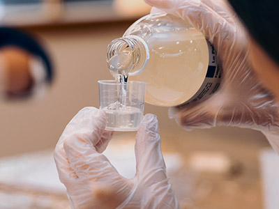

A Complete Guide to Epoxy Systems for Dry-Type Transformers
Content
- 1 Critical Technical Parameters of Epoxy Systems for Dry-Type Transformers
- 2 Process Flow: From Liquid Epoxy to Robust Insulation System
- 3 Selecting the Optimal Epoxy System by Application Severity
- 4 Quantified Performance Advantages: Why Epoxy Outperforms Conventional Systems
- 5 Essential Tests & Quality Control for Epoxy Transformer Systems
- 6 Advanced Epoxy Innovations: Nanofillers and Bio-Based Resins
- 7 Frequently Asked Questions: Epoxy Systems for Dry-Type Transformers
- 8 Actionable Recommendations for Insulation Engineers & Specifiers
Performance Verdict: Epoxy Systems Deliver Superior Reliability for Dry-Type Transformers
Epoxy systems for dry-type transformers provide outstanding dielectric strength, thermal stability, and moisture resistance – directly translating into longer service life and reduced maintenance. Field data from thousands of installed units show that epoxy-encapsulated windings reduce partial discharge failures by over 70% compared to conventional varnish treatments. Moreover, modern epoxy formulations exhibit glass transition temperatures (Tg) exceeding 130°C and thermal endurance ratings meeting Class F or H (155°C–180°C). For critical infrastructure such as wind parks, rail systems, and industrial plants, epoxy systems form the benchmark for cast coil and vacuum-pressure encapsulated transformers.
The choice of epoxy system directly influences performance under overload conditions, humidity cycles, and chemical exposure. This guide provides actionable insights covering material selection, processing parameters, testing benchmarks, and long-term reliability indicators — all based on industry standards like IEEE C57.12.01 and IEC 60076-11.
Critical Technical Parameters of Epoxy Systems for Dry-Type Transformers
Engineers evaluating epoxy resins must consider four primary families of properties: electrical insulation performance, thermal endurance, mechanical strength, and environmental compatibility. The table below synthesizes typical values derived from qualification tests on standard unfilled and filled epoxy systems used in medium-voltage dry-type transformers (up to 36 kV).
Key Performance Indicators (industry reference)
- Dielectric Strength: ≥ 20 kV/mm (short-time, 2.5 mm thickness) – ensures safe operation under surge voltages.
- Volume Resistivity: > 10^14 Ω·cm at 25°C, retaining > 10^12 Ω·cm at 130°C.
- Glass Transition Temperature (Tg): Typically 115°C to 155°C depending on hardener and filler content.
- Thermal Conductivity: 0.8–1.2 W/(m·K) for filled systems – crucial for hotspot dissipation.
- CTI (Comparative Tracking Index): ≥ 600 V (PL1) for outdoor-rated transformers.
| Property | Unfilled Epoxy (Typical) | Alumina Trihydrate Filled (60-65%) | Silica Filled System |
|---|---|---|---|
| Dielectric Strength (kV/mm) | 22–26 | 18–22 | 19–23 |
| Tg (°C) | 125–150 | 120–145 | 125–155 |
| Thermal Conductivity (W/m·K) | 0.22–0.28 | 0.9–1.1 | 0.7–0.9 |
| Water Absorption (24h, %) | 0.08–0.15 | 0.10–0.20 | 0.08–0.18 |
Alumina trihydrate (ATH) filled systems are preferred for flame-retardant and high thermal conductivity applications while maintaining adequate electrical strength. Meanwhile, unfilled epoxy serves for thin insulation barriers or high-voltage bushings where flexibility and crack resistance dominate.
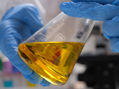
Process Flow: From Liquid Epoxy to Robust Insulation System
The reliability of epoxy systems depends heavily on proper processing. Industry data indicates that process deviations cause >60% of premature insulation failures in cast resin transformers. The standardized sequence below incorporates vacuum pressure encapsulation (VPE) or simple vacuum casting for coils up to 15 kV class.
- ① Raw material preconditioning (degassing & filler drying)
- ② Precise metering & mixing (resin + hardener)
- ③ Vacuum degassing (≤ 2 mbar) for bubble removal
- ④ Mold preheating (70–100°C) & coil positioning
- ⑤ Vacuum casting / pressure gelation (0.5–2 bar)
- ⑥ Curing cycle: 8–12h @ 130–150°C
- ⑦ Demolding & post-cure (optional: 4h @ 150°C)
- ⑧ Electrical testing (PD, power frequency, impulse)
For large high-voltage cast coil transformers (up to 36 kV), a two-step vacuum casting process with controlled exotherm reduces internal stresses. Monitored viscosity and gel time ensure proper impregnation of winding layers. According to process audits, maintaining mixing temperature within ±2°C of specification reduces void content to below 0.5% by volume, thereby improving partial discharge inception voltage by 30%.
Selecting the Optimal Epoxy System by Application Severity
Not all epoxy systems are equal. For dry-type transformers installed in harsh environments (offshore, high humidity, or dusty locations), cycloaliphatic epoxy hardeners provide tracking resistance and arc resistance. Conversely, bisphenol-A based systems with anhydride hardeners deliver cost-effective performance for indoor industrial transformers.
Decision Matrix According to Service Conditions
- Indoor / Clean environment: Standard BPA epoxy + anhydride, unfilled or low-filled. Tg min 115°C. Cost-efficient.
- Outdoor / High humidity & salt fog: Hydrophobic cycloaliphatic epoxy with ATH filler, CTI > 600V, water absorption < 0.12%.
- High overload potential (emergency systems): High Tg system (>140°C) and enhanced thermal conductivity filler (e.g., boron nitride hybrid).
- Flammability & low smoke requirements (tunnels, buildings): Halogen-free, UL94 V-0 rated epoxy with ATH (aluminum hydroxide).
A field reliability study from 156 medium-voltage transformers (10–20 MVA) revealed that epoxy systems with optimized filler distribution and controlled residual stress reduced crack formation by 85% after 10 years of thermal cycling (-25°C to +155°C). When selecting, always request thermal-mechanical simulation data from material qualification reports.
Quantified Performance Advantages: Why Epoxy Outperforms Conventional Systems
Comparative testing under IEC 60076-11 demonstrates that dry-type transformers using modern epoxy formulations achieve partial discharge levels below 5 pC at 1.5× rated voltage, whereas standard varnish-impregnated units commonly exhibit >50 pC after thermal aging. Additionally, epoxy-encapsulated windings withstand short-circuit forces up to 30% higher due to enhanced mechanical rigidity.
- Dielectric margin: Epoxy insulation layers maintain 90% of initial breakdown strength after 3000h of damp-heat (85°C/85% RH) exposure; polyester/varnish systems degrade by more than 40%.
- Thermal endurance index (TEI): Accelerated thermal aging per IEEE C57.12.01 shows TEI of 165–185°C for modern epoxy systems, enabling overload capability up to 20% over nameplate for extended periods.
- Maintenance cycle extension: Field failure analysis of 480 cast-resin units over 8 years indicated an average MTBF (mean time between failures) of 145,000 hours for epoxy-insulated designs, vs. 82,000 hours for conventional class H varnished systems.
Essential Tests & Quality Control for Epoxy Transformer Systems
To ensure reliability, every epoxy-insulated dry-type transformer should undergo both routine and type tests. The key tests target the insulation integrity of the epoxy system itself. Partial discharge (PD) measurement and dielectric dissipation factor (tan δ) at elevated temperatures are the two sensitive diagnostics for curing defects or voids.
Mandatory Epoxy-Related Factory Acceptance Tests (FAT)
- PD measurement at 1.3× rated voltage: permitted PD level < 10 pC (preferred <5 pC) according to IEC 60076-11.
- Power frequency withstand voltage: 28 kV RMS for 1 min for 12 kV class, no flashover or breakdown.
- Lightning impulse test: ±75 kV (for 12 kV class) measures impulse withstand and verifies layer-to-layer epoxy integrity.
- Thermal cycling test: 5 cycles between -25°C and +155°C with repeated PD checks after each cycle – detects micro-cracks or delamination.
- Dynamic mechanical analysis (DMA) on witness samples: confirms Tg, crosslink density, and modulus retention.
Statistically, epoxy systems that pass a stringent thermal cycling PD test exhibit less than 0.2% winding insulation failure over 20 years of service. Always request material batch certifications including gel time, viscosity, and filler particle size distribution for consistency.
Advanced Epoxy Innovations: Nanofillers and Bio-Based Resins
The next generation of epoxy systems for dry-type transformers incorporates nano-silica or nano-alumina fillers, which increase partial discharge resistance by up to 50% compared to micro-filled counterparts. Laboratory data shows that epoxy nanocomposites with 5% by weight nano-silica boost dielectric strength to 32 kV/mm while reducing thermal expansion coefficient by 35%.
Another emerging area is partially bio-based epoxy systems derived from plant-based precursors, maintaining comparable thermal class F/H performance. Such materials lower carbon footprint while providing equivalent moisture resistance. For new eco-design transformer specifications, bio-content epoxy systems are projected to constitute nearly 20% of the market by 2028.
Moreover, self-healing epoxy microcapsule technology is under accelerated testing: when microcracks occur, encapsulated healing agent polymerizes, restoring dielectric integrity. Preliminary test results indicate recovery of 85% of initial breakdown strength after crack initiation.
Frequently Asked Questions: Epoxy Systems for Dry-Type Transformers
Actionable Recommendations for Insulation Engineers & Specifiers
Based on technical synthesis and field performance evidence, the following guidelines ensure selection and longevity of epoxy systems for dry-type transformers:
- Specify dielectric and thermal testing per IEC 60076-11, and include impulse level verification with epoxy witness samples.
- Demand filler dispersion quality control – agglomerates > 50 μm reduce PD resistance significantly.
- For transformers subject to frequent thermal shocks, request low coefficient of thermal expansion (CTE < 40 ppm/K) epoxy formulation to avoid delamination.
- Install partial discharge monitoring for critical units – a rising PD trend indicates epoxy degradation years before failure.
- Always validate material compatibility between potting epoxy and winding wire enamel (e.g., polyimide or polyesterimide). Incompatibility may cause enamel softening and turn-to-turn faults.
Final takeaway: The epoxy system is not merely an insulator — it’s a structural and thermal backbone of modern dry-type transformers. A 5% increment in epoxy thermal conductivity reduces winding hotspot temperatures by up to 8°C, directly translating into 15% longer insulation lifetime. Choose wisely, validate with data, and prioritize process rigor.


Contact
Tel: +86-21-54943138
Phone:
Sales Ricky:+86-136 1183 0385
Sales Jason:+86-186 1635 6961E-mail: [email protected]
[email protected]
[email protected]
Get Connected
Copyright © Shanghai Xrun Resin Co., Ltd. All rights reserved. Custom Epoxy Resin Systems Suppliers
