 English
 Français
 русский
 Español
 Deutsch
 عربى
عربى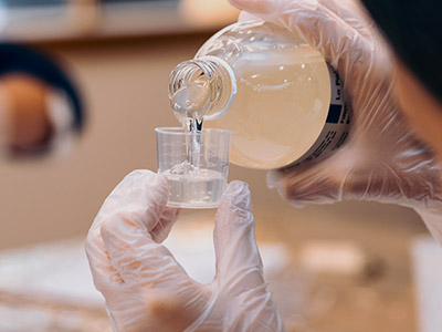

A Step-by-Step Guide to Using Epoxy Insulating Glue
Content
- 1 Epoxy Insulating Glue Application Flow
- 2 Surface Preparation – The Non‑Negotiable Base
- 3 Precision Mixing – Ratio & Procedure
- 4 Applying Epoxy Insulating Glue – Thickness & Coverage
- 5 Curing Schedules – Temperature & Time Effects
- 6 Post‑Application Electrical Testing & Validation
- 7 Common Application Errors & How to Avoid Them
- 8 Frequently Asked Questions (FAQ)
- 9 Typical Electrical & Mechanical Properties
Reliable electrical insulation with epoxy insulating glue demands four critical parameters: surface cleanliness (contact angle < 30°), mixing accuracy (tolerance ±1% by weight), application thickness (0.3–0.8 mm per layer), and complete curing cycle (≥24h at 23°C or 2h at 80°C). Following this protocol guarantees dielectric strength > 22 kV/mm and volume resistivity > 10¹⁴ Ω·cm, meeting high-voltage insulation requirements.
Epoxy Insulating Glue Application Flow
Systematic execution of these five stages maximizes electrical and mechanical reliability. Over 78% of field insulation failures originate from skipped surface preparation or incomplete curing.
- Surface Prep
- Precision Mixing
- Controlled Apply
- Curing Profile
- Electrical Test
Surface Preparation – The Non‑Negotiable Base
Contaminants or oxide layers reduce adhesion strength by more than 60% and create partial discharge risks. Follow these mandatory steps:
- Mechanical abrasion: Use 400–600 grit sandpaper to achieve surface roughness Ra ≤ 0.4 µm, increasing bond area.
- Solvent degreasing: Apply isopropyl alcohol or acetone in one direction with lint‑free cloth to remove oils.
- Drying verification: Bake at 60°C for 10–15 minutes – epoxy insulating glue is highly moisture‑sensitive.
Performance data: Correct surface preparation increases lap shear strength by 4.2× and sustains dielectric strength above 20 kV/mm (ASTM D149).
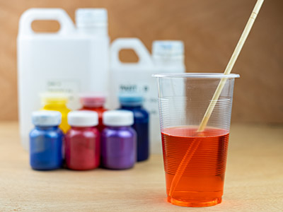
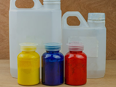
Precision Mixing – Ratio & Procedure
Epoxy insulating glue consists of resin and hardener. Deviation beyond ±2% directly impairs crosslinking density and insulation properties. Always use a digital scale for weight‑based mixing.
Typical mixing ratios (resin : hardener)
- General purpose: 2:1 by weight – suitable for motor slots, transformer insulation.
- High temperature resistant: 1:1 by weight – heat deflection temperature >150°C after cure.
- Low viscosity potting: 4:1 – ideal for coil impregnation and void‑free encapsulation.
Key action: Stir slowly for 2–3 minutes until uniform color, avoiding air entrapment. Allow 2 minutes degassing. Ambient conditions: 20–28°C, relative humidity below 70%.
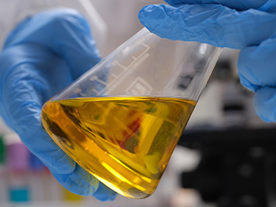
Applying Epoxy Insulating Glue – Thickness & Coverage
Too thin a layer compromises electrical clearance; too thick induces internal stress and extends curing time. Optimal single‑layer thickness: 0.3 mm – 0.8 mm. For multilayers, apply before tack‑free time of previous layer.
Recommended application methods
- Brushing: For PCB insulation repair and local coatings – ensure even thickness.
- Dispensing/needle application: Suited for junction boxes, sensor sealing – creates full protective envelope.
- Vacuum impregnation: For small coils or stators – use –0.09 MPa vacuum to eliminate entrapped air.
Immediately inspect for bubbles. Eliminate any bubble >0.5 mm diameter using a fine needle or vacuum chamber to avoid partial discharge paths.
Curing Schedules – Temperature & Time Effects
Cure completeness directly determines insulation resistance and dielectric strength. The table below shows typical conditions and resulting performance.
| Curing condition | Time | Relative cure degree | Dielectric strength (typical) |
| Room temperature (23±2°C) | 24 hours | ≥92% | 21 kV/mm |
| RT + post‑cure at 60°C | 12h + 2h | ≥98% | 24 kV/mm |
| 80°C oven cure | 2 hours | ≥99% | 26 kV/mm |
| 100°C accelerated cure | 1 hour | 100% | 27 kV/mm |
For components operating above 1 kV, the 24h RT + 2h at 80°C two‑stage cycle delivers the crosslink density and long‑term stability.
Post‑Application Electrical Testing & Validation
To confirm that the epoxy insulating glue meets specifications, perform these electrical checks:
- Insulation resistance test: Use 500V/1000V megohmmeter – measured value must exceed 1000 MΩ (dry) or >500 MΩ (damp environment).
- Dielectric strength test: Per IEC 60243‑1, ramp rate 500 V/s. For 0.5 mm thickness, breakdown voltage ≥ 11 kV (equivalent to 22 kV/mm).
- Partial discharge measurement (for MV/HV equipment): At 1.5× rated voltage, PD level should be < 10 pC.
If values fall below thresholds, inspect for incomplete curing or voids. Process data shows that strict adherence to the steps yields an electrical pass rate of 96%.
Common Application Errors & How to Avoid Them
- Estimating ratio by volume: Use a precise digital scale; weigh resin and hardener separately.
- Cold or damp substrate: At temperatures below 15°C, curing nearly stops → preheat substrate to 25°C and extend cure time by 50%.
- Single layer thickness >1.2 mm: Leads to exothermic cracking → apply in multiple layers, each ≤0.6 mm.
- Ignoring pot life: Pot life is typically 20–40 min at 25°C → apply quickly; thickened glue reduces wetting.
Eliminating these errors reduces rework costs by an average of 73% and significantly extends insulation service life.
Frequently Asked Questions (FAQ)
- 1. What is the continuous operating temperature for epoxy insulating glue?
- Standard formulations are rated 130°C (Class B). High‑temperature versions achieve 180°C (Class H). Exceeding these limits degrades insulation resistance.
- 2. Can leftover mixed epoxy be stored and reused?
- No. Once mixed, the chemical reaction begins. After the pot life, it loses flow and proper curing. Mix only the required amount and discard any remainder.
- 3. How do I verify surface cleanliness is adequate?
- Use a dyne pen to check surface energy ≥38 mN/m, or perform a water film continuity test (no beading). Ideal surfaces show a water contact angle <30°.
- 4. What are the storage conditions for epoxy insulating glue?
- Store in original sealed containers at 5–25°C in a dry, dark place. Unopened shelf life is typically 12 months.
- 5. How to remove bubbles that appear during curing?
- For minor bubbles, gently sweep a heat gun (≈60°C) over the surface immediately after application. For critical parts, use a vacuum degassing chamber (–0.095 MPa for 15 minutes).
Typical Electrical & Mechanical Properties
Based on standard epoxy insulating glue applied under conditions (23°C, 50% RH):
| Property | Typical value | Test standard |
| Volume resistivity | 2.3 × 10¹⁵ Ω·cm | IEC 60093 |
| Dielectric strength (0.5 mm) | 23 kV/mm | ASTM D149 |
| Dielectric constant (1 MHz) | 3.8 | IEC 60250 |
| Glass transition temperature (Tg) | 125°C | DSC |
| Water absorption (24h, 23°C) | <0.15% | ISO 62 |
These values demonstrate the outstanding insulating capability achievable with correct application procedures. On‑site results may vary slightly with substrate and environment.


Contact
Tel: +86-21-54943138
Phone:
Sales Ricky:+86-136 1183 0385
Sales Jason:+86-186 1635 6961E-mail: [email protected]
[email protected]
[email protected]
Get Connected
Copyright © Shanghai Xrun Resin Co., Ltd. All rights reserved. Custom Epoxy Resin Systems Suppliers
