
 English
 Français
 русский
 Español
 Deutsch
 عربى
عربى




Best Epoxy Resin Viscosity for Transformer Casting: Selection and Testing Guide
Content
- 1 Why Viscosity Sets the Ceiling on Casting Quality
- 2 The Viscosity Bands That Work for Each Casting Route
- 3 Vacuum Casting and APG Pull the Target in Opposite Directions
- 4 How to Measure Viscosity So the Number Means Something
- 5 Formulation Levers That Move Viscosity
- 6 The Filler Trade-off Between Viscosity and Thermal Conductivity
- 7 A Process Window Checklist Before Every Casting Run
- 8 Troubleshooting Viscosity-Related Defects
- 9 Matching Viscosity to the Component Being Cast
- 10 Validation and Lot Control
- 11 Frequently Asked Questions
- 11.0.1 Q1: What is the best epoxy resin viscosity for transformer casting?
- 11.0.2 Q2: Should viscosity be measured at room temperature or at the casting temperature?
- 11.0.3 Q3: Can a lower viscosity actually increase void content?
- 11.0.4 Q4: How does filler loading shift the viscosity window?
- 11.0.5 Q5: What pot life is realistic for vacuum casting?
A transformer casting can pass a visual inspection and still fail partial discharge testing months later, and the reason is often hidden inside one process variable that nobody wrote down: the viscosity of the mixed resin at the moment it entered the mold. Voids that never escaped, glass cloth that never wetted out, and filler that settled into a dense zone beneath the core all begin as a rheology problem.
There is no universal best viscosity for transformer casting. The right number depends on the casting route, the geometry being impregnated, the filler loading, the gel time of the system, and the temperature at which the mold is held. A vacuum-cast dry-type coil and an APG-molded insulation part are processed under conditions that demand almost opposite flow behavior from the same family of materials.
This article sets out how to identify the working viscosity band for a given process, how to measure it in a way that predicts shop-floor behavior, how formulation choices move the number, and how to confirm that a new resin lot still behaves like the last approved one.
Why Viscosity Sets the Ceiling on Casting Quality
Viscosity is the resistance of a liquid to flow, normally reported as dynamic viscosity in centipoise (cP) or in millipascal seconds. In a filled, reactive epoxy system it is not a fixed material property. It changes with temperature, with shear rate, and with time as the cure reaction advances. A single figure on a datasheet is a snapshot taken under one set of conditions, not a description of how the material will behave inside a mold.
Four outcomes in a transformer casting are controlled directly by the viscosity window the resin passes through between mixing and gelation:
- Impregnation depth. Resin has to penetrate between conductor turns, through glass cloth, and into mica tape. If viscosity is still high when the flow front reaches the inner layers, movement stops and leaves dry channels that later become partial discharge sites.
- Void escape. Air bubbles rise through the resin and out of the cavity only if the resin is thin enough and the interval before gelation is long enough. Viscosity and gel time must be tuned as a pair, never separately.
- Filler stability. Silica and alumina are denser than the resin. A low-viscosity system that stays fluid for hours allows settling, which produces a gradient in thermal conductivity and mechanical properties across a thick section.
- Internal stress. The temperature at which the resin gels determines how much shrinkage stress is locked into a rigid casting, and that in turn drives crack resistance after demolding.
A datasheet viscosity figure describes a liquid. A process viscosity window describes a manufacturing capability. Only the second one can be controlled on a production line.
The Viscosity Bands That Work for Each Casting Route
Different casting routes place the working viscosity in completely different ranges, because the driving force for filling the cavity is different in each case. The table below summarizes the bands that are commonly used as starting points, always measured on the mixed resin at the dispensing temperature.
| Process route | Typical mixed viscosity | Dispensing temperature | Primary constraint |
|---|---|---|---|
| Vacuum casting of dry-type coils | 200 to 800 cP | 60 to 80 °C | Wet-out of foil, glass, and mica before gel |
| Automatic pressure gelation | 800 to 2500 cP | 40 to 60 °C | Fast fill under pressure with short cycle time |
| Vacuum encapsulation of instrument transformers | 300 to 1200 cP | 60 to 75 °C | Crack-free surface and no filler segregation |
| Room-temperature potting | 1500 to 6000 cP | 20 to 30 °C | Long open time with limited degassing capability |
| Composite impregnation of rods and tubes | 400 to 1500 cP | 25 to 60 °C | Fiber wet-out and release of trapped air |
These bands are starting points for trials, not specifications. A 900 cP system at 70 °C can outperform a 500 cP system if its gel time profile keeps the resin fluid long enough for the vacuum hold to do its work.
Vacuum Casting and APG Pull the Target in Opposite Directions
The two dominant production routes for power insulation parts sit at opposite ends of the viscosity map, and confusing them is one of the most common causes of a failed process transfer.
Vacuum casting of dry-type transformer coils
Vacuum casting relies on low pressure to strip air from the winding and from the resin itself, then on a modest pressure stage to collapse the bubbles that remain. The resin must be thin enough at the injection temperature to travel through long axial channels and to wet every layer of reinforcement. Typical conditions hold the resin between 60 and 80 °C, with a vacuum stage below roughly 5 mbar before the pressure stage is applied.
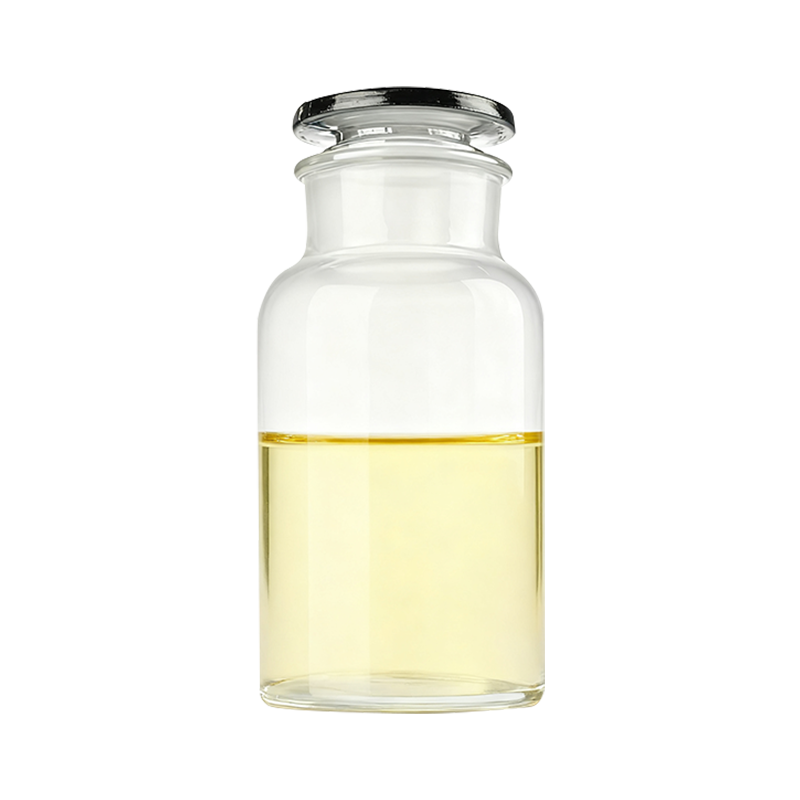 HE-411 High Tg Vacuum Casting Epoxy Resin for HV InsulationHigh-Tg vacuum-casting epoxy for HV insulation components, with solid/liquid resin-curing agent options and long gel time for demanding impregnation processes.View Product →
Choosing a vacuum casting system therefore means balancing two requirements that fight each other. The resin must stay fluid long enough to fill and degas, yet it must reach a high glass transition temperature after cure to survive thermal cycling in service. Systems built for this compromise keep a low working viscosity in the 70 °C region while delivering a high Tg after a staged cure. Pushing viscosity too low is not free either: below about 150 cP, filler settling and resin drainage before gel become real risks.
APG and pressure gelation
Automatic pressure gelation works in the opposite way. Resin is injected under pressure, often between 20 and 40 bar, into a mold held at 120 to 160 °C, and the part gels within minutes. A higher viscosity in the range of 800 to 2500 cP is not a defect here; it is an advantage, because the resin must not drain from the cavity or create turbulence before the gel front stabilizes. The limiting factor in APG is usually thermal rather than rheological: the resin must fill every corner before the hot mold raises its viscosity beyond the point of flow.
How to Measure Viscosity So the Number Means Something
Viscosity data becomes useful only when the measurement conditions are recorded with it. Filled epoxy is shear-thinning, so the reading depends on how fast the spindle turns and on the geometry of the measuring system.
- Fix spindle and speed, and report both. The same resin can read 900 cP at one speed and 600 cP at a faster one. A number without the measuring conditions cannot be compared with anything.
- Condition to the real process temperature. A shift of 10 °C in a filled system can change viscosity by 40 percent or more, which is larger than the difference between many commercial grades.
- Measure the mixed system. Individual component viscosities are useful for pump and metering calculations, but only the mixed value predicts mold behavior.
- Record a viscosity-life curve, not a single point. The time required for the mixed resin to double its initial viscosity is a practical indicator of how long a vacuum stage can be sustained.
- Pair every viscosity reading with a gel time. Two lots with identical viscosity but different gel times will behave completely differently during filling.
For incoming inspection, one reference point is sufficient: a fixed temperature such as 60 °C, a fixed spindle and speed, and a tolerance band narrow enough to catch genuine drift. Anything wider than about 15 percent around the approved baseline tends to hide real variation.
Formulation Levers That Move Viscosity
When a resin does not sit in the required band, there are five practical levers. Each one changes something else as well, which is why the choice should be made against the full process window rather than against viscosity alone.
- Base resin chemistry. Standard bisphenol-A epoxy and novolac-modified resins differ in initial viscosity, in reactivity, and in the Tg they reach after cure. Novolac types typically deliver higher heat resistance at the cost of a steeper viscosity rise during processing.
- Reactive diluents. These reduce viscosity without introducing solvent, but most of them also lower the glass transition temperature and increase shrinkage. They are a tool for fine adjustment, not a substitute for temperature control.
- Filler type, loading, and surface treatment. This is the largest single lever. Fumed silica raises viscosity sharply and adds thixotropy, while surface-treated crystalline silica can be loaded heavily with a more predictable increase.
- Accelerator level. A faster gel gives less time for filler to settle but also shortens the window available for impregnation and degassing. Accelerator changes must be validated with a trial casting.
- Process temperature. Within the working range, viscosity roughly halves for every 15 to 20 °C of additional heat, which makes temperature the fastest and most reversible adjustment available on the shop floor.
The Filler Trade-off Between Viscosity and Thermal Conductivity
Thermal conductivity in a casting comes from the filler network, and that network is built by loading the resin with dense mineral particles. Higher loading means better heat removal, but it also means higher viscosity, more shear-thinning behavior, and a narrower processing window.
| Filler strategy | Mixed viscosity | Thermal conductivity | Practical consequence |
|---|---|---|---|
| Low loading or unfilled | Below 600 cP | 0.2 to 0.4 W/mK | Easy filling, higher shrinkage, limited heat removal |
| Medium loading | 600 to 1500 cP | 0.6 to 1.0 W/mK | Balanced filling behavior and thermal performance |
| High loading, treated filler | 1500 to 4000 cP | 1.5 to 2.0 W/mK | Requires higher process temperature and toughened formulations |
 HE-8523 Low-Viscosity Adjustable Epoxy Resin for Dry-Type TransformersAdjustable low-viscosity epoxy system for dry-type transformer insulation, offering curing agent, toughening agent, and accelerator options to balance filler loading and processing.View Product →
For dry-type transformers, the usual solution is not to choose between flow and heat removal but to adjust the formulation so that both are satisfied. Systems described as low-viscosity with adjustable formulation allow the filler package to be tuned to the thermal class required by the design, keeping the mixed viscosity inside the band that the existing vacuum plant can handle. The decision should be made together with the winding design team, because a thicker insulation layer changes the thermal path as much as the filler does.
A Process Window Checklist Before Every Casting Run
- Confirm the mixed viscosity at the actual dispensing temperature, not at room temperature.
- Confirm the gel time on the same sample used for the viscosity reading.
- Check that the vacuum level reaches its target before the resin front enters the winding.
- Verify that the mold temperature is stable across the whole cavity, not only at the inlet.
- Confirm the pressure stage starts before the resin begins to thicken noticeably.
- Record the interval between mixing and the start of injection, and keep it constant between runs.
- Check filler dispersion visually on a cured sample from the same batch.
- Compare the current lot against the approved baseline before releasing the run.
Troubleshooting Viscosity-Related Defects
Most casting defects carry a rheological signature. The table below links common symptoms to the viscosity conditions that usually produce them.
| Symptom | Likely viscosity cause | Direction of correction |
|---|---|---|
| Voids clustered near winding ends | Viscosity too high when the flow front arrives | Raise resin temperature or extend the vacuum hold |
| Dry reinforcement layers | Premature gel before full impregnation | Reduce accelerator level or lower the mold temperature |
| Dense band at the bottom of a tall mold | Viscosity too low for the open time | Increase filler loading or shorten the filling stage |
| Cracks after demolding | Gelation at too high a temperature | Adjust the cure schedule and review the viscosity profile |
| Surface wrinkles and flow lines | Uneven viscosity rise across the cavity | Improve mold temperature uniformity and check the mixing ratio |
| Partial discharge above specification | Micro voids retained after the pressure stage | Lower viscosity at injection and verify the pressure stage timing |
Matching Viscosity to the Component Being Cast
Geometry decides as much as chemistry. A tall, thin coil with long axial flow paths needs a lower viscosity and a longer open time than a compact disk insulator. Components with dense mica or glass reinforcement need more time under vacuum so the resin can wet every layer. Components with a large thermal mass, such as a reactor winding, need a viscosity that stays low long enough to fill but rises quickly enough afterwards to limit exotherm.
- Dry-type transformer coils: 250 to 600 cP at 65 to 75 °C, with a vacuum hold sized to the winding thickness.
- Current and voltage transformers: 300 to 900 cP at 60 to 70 °C, prioritizing surface finish and crack-free demolding.
- Switches, tie rods, and compact parts: 800 to 2500 cP, where mechanical strength and cycle time dominate.
- Reactors and filter components: 400 to 1000 cP, with close attention to filler settling in tall molds.
The requirements differ enough between product families that most manufacturers maintain separate material grades rather than one universal resin. A review of typical transformer insulation applications shows how widely the processing conditions vary across a single equipment category.
 HE-2841A Low-Viscosity Crack-Resistant Epoxy Resin for CT/VTLow-viscosity crack-resistant epoxy for CT/VT insulation and APG or vacuum casting, with curing agent HF-2841B and Tg above 75.View Product →
For instrument transformers, the twin demands of low viscosity for impregnation and high crack resistance after cure are usually met by a system that combines a low working viscosity with a toughened curing agent. This pairing is what allows a thin, complex casting to survive thermal cycling without surface cracks.
Validation and Lot Control
Once a viscosity window has been established, the remaining task is keeping production inside it. That requires a reference method, a defined sampling plan, and a decision rule for lots that fall outside the band. A resin lot should never be released to the line on the basis of a certificate alone; a single reference measurement at the defined temperature is enough to confirm that the material matches the property that was originally validated.
The most reliable approach is to treat viscosity, gel time, and mixing ratio as one control set. If a supplier changes any of the three, the change should be revalidated with a trial casting that includes the actual winding geometry, because a resin that performs well in a test block can still fail in a long axial flow path. This is the same discipline applied during formulation development in an insulation materials research and development program, where viscosity targets are set against a specific process before the material is released.
Consistency matters more than a low number. A stable 700 cP system that behaves identically on every lot will outproduce an unstable 400 cP system every time.
Frequently Asked Questions
Q1: What is the best epoxy resin viscosity for transformer casting?
There is no single value. Vacuum-cast dry-type transformer coils generally work between 200 and 800 cP at 60 to 80 °C, while APG molding normally runs between 800 and 2500 cP at 40 to 60 °C. The correct figure is the one that lets the resin wet out the winding and release trapped air before gelation, and it should be confirmed with a trial casting rather than taken from a datasheet.
Q2: Should viscosity be measured at room temperature or at the casting temperature?
Always at the casting temperature. A filled epoxy is strongly temperature dependent, and a room-temperature reading says very little about flow inside a mold held at 70 °C. Recording the temperature alongside every reading is what makes the data comparable between lots and between suppliers.
Q3: Can a lower viscosity actually increase void content?
Yes. An excessively low viscosity can drain from the cavity before the gel front stabilizes, allow heavy filler to settle, and create fast turbulent flow that drags air into the winding. The objective is a controlled window, not the lowest achievable number.
Q4: How does filler loading shift the viscosity window?
Raising mineral filler from roughly 40 to 65 percent by weight multiplies mixed viscosity several times and increases shear-thinning behavior. Thermal conductivity improves, but the impregnation and degassing windows narrow, so the process temperature usually has to be raised to compensate.
Q5: What pot life is realistic for vacuum casting?
Judge by the viscosity-life curve rather than by a single pot-life figure. A practical rule is to plan the fill and vacuum stages so that the cavity is closed before the mixed viscosity doubles, which keeps the resin fluid enough to release air without extending the cycle unnecessarily.
Viscosity is not a property to be selected once and forgotten. It is the variable that connects resin chemistry, filler package, mold temperature, vacuum performance, and curing schedule into a single working window. Define that window in numbers, measure against it on every lot, and the defects that seemed random will start to look predictable, which is the point at which they become preventable.



Contact
Tel: +86-21-54943138
Phone:
Sales Ricky:+86-136 1183 0385
Sales Jason:+86-186 1635 6961E-mail: [email protected]
[email protected]
[email protected]
Get Connected
Copyright © Shanghai Xrun Resin Co., Ltd. All rights reserved. Privacy Custom Epoxy Resin Systems Suppliers
